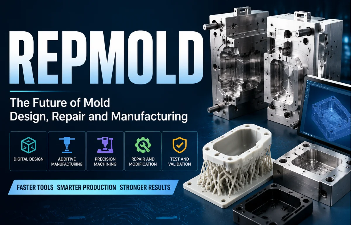
Repmold is best understood as an emerging, non-standard label for a digitally connected approach to designing, reproducing, testing, and manufacturing molds or molded parts. In plain language, it combines tools such as CAD, 3D scanning, mold-flow simulation, additive manufacturing, CNC machining, and production data in one coordinated workflow.
The term is not used in established technical literature as a process name in the same way as injection molding, rotational molding, or compression molding. The closest recognized concepts are rapid tooling, digital manufacturing, additive tooling, and reverse engineering. I use repmold here as a practical umbrella term for those connected activities—not as one machine, material, or universal process. NIST describes additive manufacturing as production from digital designs, while its technical literature uses “rapid tooling” for molds produced with additive methods.
What Does Repmold Actually Mean?
Online definitions vary. Some sources describe repmold as a reusable mold copied from a master pattern; others present it as smart mold manufacturing, mold repair, or a combination of rapid prototyping and digital production. That inconsistency suggests repmold currently functions more like an industry-facing concept than a standardized technical category.
A useful working definition is:
Repmold is a digital mold-development workflow used to create, reproduce, modify, validate, or repair tooling more quickly by connecting digital design with suitable fabrication and inspection methods.
A project may begin with a new CAD model, an old physical tool, a master pattern, or a finished component that needs to be reproduced. The output might be a prototype mold, short-run production tool, repaired insert, casting pattern, or digitally archived replacement tool.
Repmold Is Not One Manufacturing Method
A common mistake is treating repmold as if it replaces injection molding or 3D printing. It does not. It describes how several methods can be organized around a digital model.
| Term | What it refers to | Relationship to repmold |
|---|---|---|
| Injection molding | Forcing molten material into a closed mold | May be the final production process |
| Rapid tooling | Producing tooling quickly, often with additive or hybrid methods | Closest established technical concept |
| 3D printing | Building an object layer by layer from digital data | Can produce patterns, inserts, molds, or fixtures |
| CNC machining | Removing material with computer-controlled tools | Used for metal tooling or final finishing |
| Reverse engineering | Reconstructing design data from an existing object | Can supply the starting geometry |
| Repmold | A connected mold-creation, repair, and validation workflow | Coordinates the methods above |
No route is ideal for every job. A printed polymer mold may suit a limited prototype run, while a hardened steel tool may still be correct for hundreds of thousands of high-pressure cycles.
How a Repmold Workflow Works
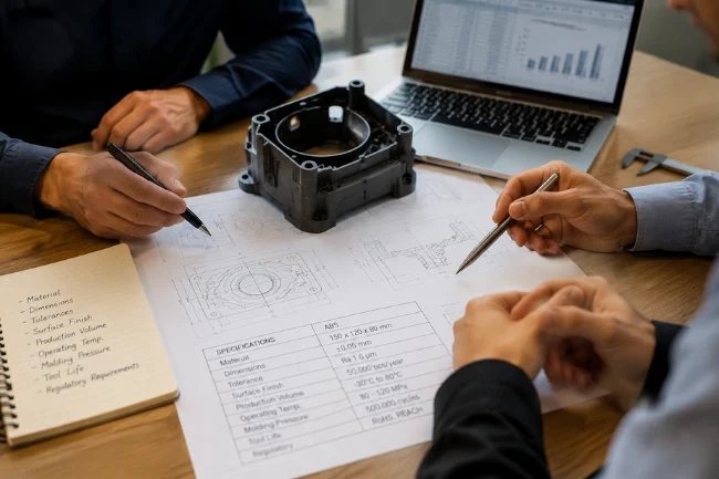
Define the Production Requirement
I start with the part’s real job rather than the technology. The team should establish material, dimensions, tolerances, surface finish, production volume, operating temperature, molding pressure, regulatory requirements, and acceptable tool life.
Without those numbers, “faster” and “cheaper” are only marketing claims. A low-cost mold that fails after a few cycles is not economical.
Create or Capture the Geometry
For a new product, engineers usually work from CAD. For an existing component or damaged mold, they may use dimensional inspection or 3D scanning, then rebuild clean design surfaces.
Scanning is not an automatic copy button. Worn edges, deformation, shrinkage, and earlier repairs can be captured as if they were intentional. Someone must decide what to preserve and what to correct.
Prepare the Mold Design
The part model is converted into mold geometry. Depending on the process, this can include draft angles, shrinkage allowances, parting lines, gates, runners, vents, ejectors, cooling channels, inserts, and clamping features.
Simulation can identify filling problems, air traps, weld lines, sink marks, uneven cooling, and warpage before tooling material is committed. Autodesk’s mold-simulation resources describe this virtual evaluation as a way to predict flow and improve mold and part design.
Choose the Tooling Route
The mold may be CNC-machined from aluminum or steel, printed in polymer or metal, cast from a printed pattern, built as a hybrid tool, or produced as a replaceable insert inside a stronger mold base.
Additive manufacturing can remove intermediate pattern-making stages in some applications. NIST notes that sand molds and cores can be printed directly from CAD data. A Department of Energy wind-blade project also demonstrated mold production in weeks rather than months, although that project-specific result is not a universal guarantee.
Finish, Inspect, and Test
Printed or rough-machined tooling may need milling, sealing, coating, polishing, heat treatment, or added hardware. Surface quality matters because tool marks can transfer to the molded part.
The first production trials reveal whether the digital assumptions match reality. Dimensions, defects, process conditions, tool wear, and corrective changes should be recorded against the approved model.
The final CAD revision, machine settings, inspection report, material batch, and maintenance history should remain connected. That digital record makes later repair or reproduction more reliable than starting from an undocumented mold.
Where Repmold Can Be Useful
Prototype and Low-Volume Production
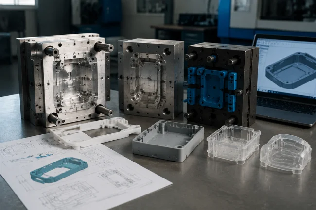
Rapid tooling is attractive when design changes are still likely, or quantities do not justify expensive long-life tooling. NIST identifies lower-volume production and customization as areas where additive manufacturing can offer improved economics.
A company preparing a market test, limited product launch, or engineering trial may not need a tool designed for millions of cycles. A faster temporary tool can provide real molded parts while the final design is still being refined.
Automotive and Composite Tooling
Automotive programs use molds and dies for prototypes, composite panels, interior parts, forming operations, and fixtures. In 2025, Oak Ridge National Laboratory reported work on 3D-printed metal molds intended to offer a faster, more flexible route for large composite automotive components.
The value is not limited to speed. Digital tooling can make it easier to revise a surface, reduce tool weight, reproduce damaged sections, or manufacture a replacement closer to the production site.
Aerospace and Wind Energy
Large composite structures can require costly patterns and lengthy tooling programs. Additively manufactured tooling has been tested for wind-blade molds and large molds used under industrial autoclave conditions.
These applications also show why repmold should not be reduced to desktop 3D printing. Large-format tooling may require reinforced materials, industrial equipment, precision machining, coatings, heating systems, and extensive testing.
Replacement and Legacy Parts
A company may have a working product but no usable CAD file for the original mold. A repmold workflow can combine scanning, redesign, modern tooling, and inspection to create a controlled replacement.
This is useful when the original supplier has closed, a tool is damaged, or only a small number of spare parts is needed. The challenge is not merely copying the shape; it is restoring design intent and verifying performance.
For example, a worn molded component may no longer match its original dimensions. Directly scanning and copying that part could reproduce years of wear. The digital model must account for intended geometry, material shrinkage, mating surfaces, and functional clearances.
Customized and Medical Products
Digital workflows can support geometry that changes for each customer or patient. Examples may include customized supports, prosthetic components, positioning devices, dental models, and tooling for limited medical production.
A customized medical device, however, is not automatically safe because it was digitally produced. Material traceability, validation, biocompatibility, sterilization, quality systems, and regulatory approval still apply.
Benefits and Trade-Offs
Repmold can shorten iteration cycles, preserve tooling knowledge, enable complex geometry, and make repair or replacement more predictable. It may also remove physical patterns from certain workflows.
Digital files make controlled revisions easier. Instead of manually modifying a pattern and hoping the change is documented correctly, a team can update the approved model, simulate the change, manufacture the revised tool, and retain a clear revision history.
The limits matter just as much. Printed tools may have restricted pressure resistance, thermal stability, surface finish, accuracy, or cycle life. Additive manufacturing can also be too slow or costly for direct mass production, which is why NIST research presents rapid tooling as support for conventional production rather than a replacement in every case.
| Decision factor | Rapid or hybrid repmold approach | Conventional production tooling |
|---|---|---|
| Best fit | Prototypes, bridge runs, repairs, changing designs | Stable, sustained high-volume production |
| Initial lead time | Often shorter, depending on finishing | Usually longer for complex hardened tools |
| Design changes | Easier before final approval | Expensive after steel is cut |
| Tool life | Depends heavily on material and process load | Can be designed for long production runs |
| Surface finish | May need sealing, machining, or polishing | High-quality finishes are well established |
| Economics | Strongest at lower volumes or urgent launches | Often strongest at high volumes |
| Main risk | Overestimating durability | High upfront cost and slow modification |
My Five-Question Repmold Readiness Test
When I assess whether the approach makes sense, I ask:
- Is the design still changing?
- Is the production volume low, uncertain, or time-sensitive?
- Can the tool material survive the real heat, pressure, chemicals, and cycle count?
- Can critical dimensions and surfaces be inspected?
- Will files, revisions, process settings, and maintenance data be controlled?
A project that answers “yes” to the first two questions may benefit from rapid or hybrid tooling. A project that cannot answer the last three is not ready, regardless of how advanced the equipment sounds.
This test also prevents a common purchasing error: selecting a process because it appears modern rather than because it matches the production requirement.
Cost, Speed, and Sustainability
There is no universal repmold price. Cost depends on size, geometry, material, printing or machining time, finishing, inserts, inspection, trials, and expected life.
The useful comparison is total delivered cost. That includes engineering, tooling, revisions, scrap, downtime, cycle time, maintenance, shipping, and launch delay. A more expensive tool can be the better choice if it produces stable parts for years.
Speed should be measured the same way. Printing a mold quickly offers little benefit if the tool then requires extensive sealing, machining, polishing, repairs, or repeated trial runs.
Sustainability also requires a whole-system view. Digital and additive methods may reduce waste, remove a pattern, lighten a tool, or support local production. NIST notes that additive manufacturing can use less material and generate less waste than many subtractive routes, but the final result still depends on energy use, failed builds, feedstock, finishing, tool life, and disposal.
A short-lived tool that must be remade several times may have a larger footprint than a durable conventional tool. Claims about sustainable manufacturing should therefore consider the complete lifecycle rather than the fabrication stage alone.
Common Repmold Mistakes
The first mistake is assuming the term describes a proprietary machine or miracle material. The second is choosing a tool only by purchase price.
Other problems include scanning a worn part without correcting it, skipping flow or thermal analysis, ignoring shrinkage, selecting printed material by room-temperature strength alone, and failing to document the approved revision.
Teams may also underestimate finishing. A mold can be dimensionally close to the CAD model yet still produce unacceptable parts because of rough surfaces, poor venting, weak edges, inadequate cooling, or an unsuitable release system.
I also question unsupported percentage claims. A supplier should explain the baseline behind any promised reduction in time, cost, or waste. A result from one large composite mold cannot automatically be applied to a small injection-mold insert.
The Future of Repmold
The useful future of repmold is not the word itself. It is the connection of design, simulation, flexible tooling, sensors, inspection, and manufacturing records.
More hybrid molds, conformal cooling, modular inserts, automated design checks, process monitoring, and digital repair histories are likely. Oak Ridge research has already explored self-heating printed molds and optimized additively manufactured tooling, showing how functions can be built into a tool rather than added later.
Manufacturers may also begin treating mold data as a long-term business asset. A well-maintained digital record could include the approved geometry, material specifications, process window, inspection results, repair history, and known wear points.
For manufacturers, the advantage will come from choosing the right combination of methods and validating the result—not from adopting a fashionable label.
Frequently Asked Questions
Is repmold a real manufacturing technology?
Repmold is an emerging, non-standard term for connected mold development; established related terms include rapid tooling, additive tooling, reverse engineering, and digital manufacturing.
Is repmold the same as injection molding?
No. Injection molding forms parts inside a mold, while repmold describes a broader workflow used to design, reproduce, repair, or manufacture tooling.
Can repmold be used for mass production?
It can support mass production through molds, inserts, or bridge tooling, but the final tool must withstand the required pressure, temperature, and cycle count.
What Materials Are Used in Repmold Projects?
Possible materials include tool steel, aluminum, printed metals, reinforced polymers, resins, silicone, sand systems, and composites, depending on the process.
Is Repmold Cheaper Than Traditional Mold Making?
Sometimes. It is often competitive for prototypes, repairs, changes, and lower-volume runs; conventional tooling may deliver better economics at high volume.
What to Do Next
Treat repmold as a decision framework, not a promise of automatic savings. Start with part requirements, volume, tool loads, and validation, then compare CNC, additive, casting, and hybrid tooling on total cost and risk.
Before selecting a supplier, ask for the proposed tool material, expected cycle life, tolerance plan, finishing method, inspection process, revision control, and evidence from a comparable application. Those answers will reveal more than any broad claim about “smart molding.”

Ethan Caldwell is a business research writer with 9+ years of experience covering entrepreneurship, market trends, business strategies, and industry insights. He focuses on creating clear, data-informed articles that help readers understand modern business concepts.